Checking the charging voltage
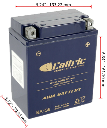
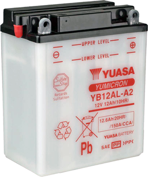
A measurement of the battery voltage can provide information about the function of the charging circuit. To do this, we set the multimeter to the 20V DC measuring range and connect it directly to the battery. If the battery condition is good, the voltage should not fall below 12.5 V. 3,000–4,000 rpm, the charging voltage should rise to a limit value of no more than 14V. Short-term measurable voltage peaks indicate a defect in the rectifier. If the charging voltage does not increase despite the increasing speed, the alternator is not delivering enough charging current.
Check the 3 phase alternator
2GV814102000
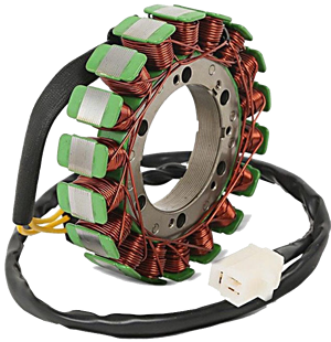
1. Checking the alternating voltages:
When switching off the ignition, we disconnect the plug connection between the alternator and regulator / rectifier.
Now we're going to connect an AC voltmeter directly to the alternator. (Measuring range 200V AC).
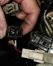
We now measure the 3 alternating voltages at an engine speed of approx. 3,000 - 4,000 rpm.
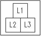
1. Engine and ignition off, connect L1 and L2 of the alternator plug to the test probes, engine on and measure.
2. Engine and ignition off, connect L1 and L3 of the alternator connector to the test probes, turn on engine and measure.
3. Engine and ignition off, connect L2 and L3 of the alternator plug to the test probes, turn on engine and measure.
Now we compare the 3 measured values.
At approx. 50–70 volts AC the alternator is OK.
If the three measured values deviate significantly from each other, the alternator is defective.
2. Check for short-circuit to ground:
If the alternator does not provide sufficient charging voltage, a ground fault in the windings may be the cause.
Symptom:
- Battery voltage weak
- The starter is still turning, but the engine still does not start
- The motorcycle cannot be started even by pushing it
Quick test without measuring device:
- Disconnect the alternator cable and start the engine without the alternator.
- If the motor then starts, there is a short to ground in the stator winding.
Test using resistance measurements:
- Engine and ignition off
- Set the multimeter to measure resistance in the 200 ohm range
- Black test tip to ground
- Red test tip to all 3 contacts of the alternator connector one after the other
- No continuity must be measurable, otherwise the stator has a short to ground.
3. Check for continuity:
Next, we test all possible connection combinations between the contacts with the test probes.
1. between L1 and L2
2. between L1 and L3
3. between L2 and L3
A consistently low resistance should always be measured (usually below 1 ohm.
If the measured value is too high, there is insufficient continuity between the windings.
With a measurement result of 0 Ohm there would be a short circuit, in both cases the stator would be defective.
If the continuity test was OK, but the previously measured AC voltage of all 3 phases was too low, the rotor is demagnetized.
Check the rectifier / regulator
3JB-81960-01
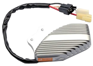
If the voltage on the battery exceeds the limit value (13.5 to 14 V) when increasing the engine speed,
the voltage regulator is defective.
To test the rectifier / regulator, disconnect it from the circuit and check the 6 diode sections in the measuring range provided on the multimeter.
1. Measuring tip red on L1 and black on plus should indicate continuity, but vice versa block completely.
2. Red on L2 and black on plus should indicate continuity, but vice versa block completely.
3. Red on L3 and black on plus should indicate continuity, but vice versa completely block.
4. Black on L1 and red on minus should indicate continuity, but vice versa block completely.
5. Black on L2 and red on minus should indicate continuity, but vice versa completely block.
6. Black at L3 and red at minus should indicate continuity, but vice versa completely block.

Check the starter relay
3AY-81940-00-00
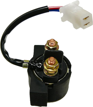
If you only hear a clacking noise when you try to start the engine, despite a well-charged battery, without the starter turning, the starter relay may be defective.
For control:.
- Disconnect the cables from the two contact nuts.
- Set the multimeter to the resistance measuring range of 200 ohms.
- Connect test probes to both contact nuts of the relay.
- Press the start switch.
A resistance of 0 ohms must now be measured on the relay.
If the measured value is well above 0 ohms, the starter relay is defective.
Otherwise the starter is probably defective.
If the relay does not click, either the control voltage is missing or the excitation coil of the relay is defective.
For testing
- Set the measuring device to the measuring range DC 20V.
- Hold test probes against the control inputs of the relay.
- Press the start switch.
If 12V can be measured, the excitation coil of the starter relay is defective.
Otherwise the start switch is probably defective.
The start switch can be checked by measuring the resistance with the multimeter with separate cable entries. If a resistance greater than 0 ohms is measured, the switch is defective.
Check the starter
3JB-81890-00-00
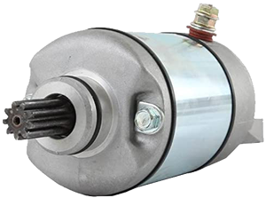
Corrosion of the connections is often the cause of a poor starter.
This is where cleaning with sandpaper and contact spray can work wonders.
If this does not help, the starter must be removed and dismantled for checking with the battery disconnected.
First check the pressure of the brush springs and the length of the carbon brushes.
Worn out carbon brushes must be replaced.
The collector is cleaned with petrol or brake cleaner and must be free of grease.
If there is visible oxidation, clean with fine sandpaper if necessary.
The collector grooves should have a depth of approx. 0.5–1 mm. If this is no longer the case, you can try to carefully recut these with a thin saw blade.
Check rotor for continuity:
- Set the multimeter to the measuring range of 200 ohms.
- Measure the resistance between two collector segments of the rotor in all possible combinations.
A resistance of less than 1 ohm must be measured.
If it is too high, there is an interruption in the rotor coil.
Check rotor for short to ground:
- Set the multimeter to the measuring range up to 2 MOhm.
- Red test tip on each collector lamella.
- Hold the black test tip on the rotor axis.
An infinitely high resistance must be measured in each case, otherwise there is a short to ground.
In both cases the rotor would be defective and would have to be replaced.
Checking the ignition
If the engine does not start even though the starter is turning the engine and a correct gasoline-air mixture has entered the engine (i.e. the spark plug becomes damp), the cause is a defect in the ignition circuit.
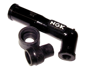
If the ignition spark is weak or absent, the cable connections, spark plugs and ignition plugs are checked first. Old candles, plugs and ignition cables should definitely be replaced.
The use of iridium spark plugs improves the starting behavior (better burn-off behavior, stronger ignition spark).
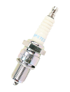
Spark plug NGK BPR7ES
If there are thin, burnt wires on the ignition coil housing, this can be the cause of leakage currents.
Moisture penetrates the ignition coil through hairline cracks and leads to short circuits.
Older ignition coils often only fail after warming up and often work again after cooling down.
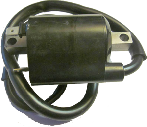
Yamaha VX 535 Virago Zündspule 4 Ohm primäry (1984 - 2003) 2GV-82310-21-00
In order to check the quality of the ignition spark, the spark gap can be determined with a spark gap tester.
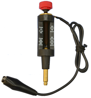
A sufficiently strong spark should jump at least 5–7 mm from the ignition cable to ground
It is not advisable to let the spark jump to the engine ground without a spark gap tester, as this can damage the TCI box and you can easily get an unpleasant electric shock while working.
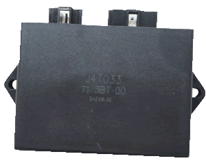
Ignition box:
Yamaha VX 535 Virago ignition unit 1987 - 1990 : 2GV-82305-20-00 : J 4 T 020 (2 coils)
Yamaha VX 535 Virago ignition unit 1991 - 2001 : 3BT-82305-00-00 : J 4 T 033 (1 coil)
If the spark plugs, spark plugs, ignition coils and cable connections are OK and still no noticeable spark skips, there is a defect in the ignition box or its control system.
The ignition box itself is a sensitive and expensive component. A check is not possible without a special measuring device.
You can therefore only check whether the cable connections are in perfect condition.
Diode Assy
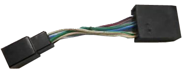
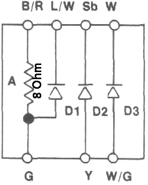
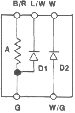
Yamahe VX 535 Virago Diode-assy
with 3 diodes 1987-1988 : 4U8-81980-M0-00 / with 2diodes 1989 - 2001 : 4H7-81980-M0-00
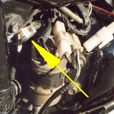
Prüfen der Impulsgeberspule
3BT-81670-00 (F007T53271)
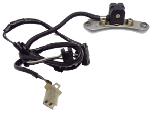
Yamaha VX 535 Virago Pick-Up assy
In the Yamaha VX 535 Virago, the ignition electronics receive their pulse from a magnetic rotor in the starter, which is synchronized with the crankshaft and controls a pulse generator ("pickup"). A pulse generator coil can be checked with the multimeter.
For a resistance measurement, we set the measuring range to 2 KOhm, disconnect the transducer, hold the test probes on its connections and compare the measured value with the workshop manual for the vehicle model.
A resistance that is too high indicates an interruption, while a resistance that is too low indicates a short circuit.
Now switch the multimeter to measuring range 2 MOhm and determine the resistance between winding and ground.
If it is not "infinite", there is a short to ground and the pulse generator coil must be replaced.
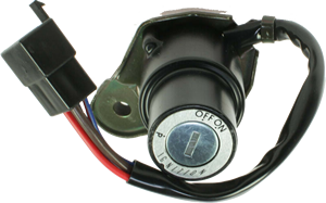
Check the switches, plugs, and cables
Corrosion and pollution cause contact resistance.
Green contact surfaces and cable connections must be completely cleaned. Often only scratching and contact spray help. If this is not sufficient, the corresponding cables, contacts and plugs must be replaced.
A resistance measurement gives more precise information about the conductivity.
In any case, first disconnect the battery, set the multimeter to the measuring range of 200 ohms, hold test probes to the cable entries of the switch or plug and measure the resistance.
If a resistance greater than approx. 0 ohms is measured, there are defects, soiling or corrosion damage.
The measurement of the voltage drop can also provide information.
To do this, select the measuring range 20 V DC voltage on the multimeter.
Detach the positive and negative cables from the consumer, hold the black test probe on the negative lead and the red test probe on the positive lead.
The undiminished battery voltage must be measured; lower values indicate errors.
Leakage currents:
If the battery discharges by itself even though the ignition is switched off, a current leak is the cause.
Leakage current can be caused, for example, in the ignition lock, a defective switch, a relay or a jammed or frayed cable. Oxidation, dirt and leaked battery acid can also cause leakage current.
Leakage current can be detected by measuring the amperage with a multimeter.
A standard multimeter must never be loaded with more than 10 A.
An amperage measurement on the positive lead to the starter, on the thick battery cable to the starter relay or on the alternator must therefore be avoided in any case!
- Switch off the ignition and disconnect the battery negative cable.
- Set the multimeter to the "Milliampere" measuring range.
- We hold the red test tip to the negative cable that has been disconnected from the battery.
- The black test tip to the negative pole of the battery.
If a current can be measured, this is already our leakage current.
The source can now be narrowed down by taking out the motorcycle fuses piece by piece.
The circuit, the fuse of which silences the measuring device, carries the leakage current and must be examined in detail.
Ground fault:
Does the rear light flash weakly when the direction indicator is activated?
Are the electrical functions not performing to their full potential?
Then there is probably a ground fault.
Often only the battery poles are corroded, this is not always immediately visible. A little pole grease protects against renewed corrosion.